Battery: The source of a device – Li-ion chargers
In today’s world where more and more devices are becoming mobile, efficient battery usage has become essential, with engineers tending to prioritise the current consumption of the device. They devise numerous ways to reduce the power consumption, because the longer the battery lasts, the greater perceived market value for the product. It is important, however to consider the battery itself.
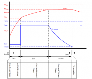
Fig. 1 – Charging profile of Li-ion battery
Selecting an appropriate battery for a particular application is essential, as the battery determines the number of hours the device can work for without needing recharging, the amount of weight it adds to the system, and how much it adds to the BOM (Bill of Material) cost. In addition to choosing the battery, proper design of charging circuitry is also crucial, because improper design can reduce the battery life or can even lead to battery failure (i.e., dangerous leakage or explosion). In this article, we will discuss how to implement a battery charger using Li-Ion technology as the example.
Li-Ion battery chargers use constant current (CC) – constant voltage (CV) profile for charging. The charging process passes through several stages to ensure the battery is charged to its full capacity, while at the same time following certain safety rules. The CC-CV profile consists of several stages:
- Pre-charge
- Activation
- Constant current
- Constant voltage
Charging begins with a pre-charge stage to check if the battery is in good condition. During this stage, a small amount of current, usually 5% to 15% of the battery capacity, is provided to the battery. If the battery voltage rises above 2.8V, then the battery is considered in good condition and the charging process transitions to the activation stage, where the same amount of current is maintained for a longer duration of time.
When the battery voltage rises above 3V, a rapid charge is initiated where a constant current equal to or less than the battery capacity is provided. This state is maintained until the battery voltage rises to full charge voltage (4.2V) or until time out; whichever is earlier. When the battery voltage reaches full charge voltage, the state is moved to a constant-voltage stage. To achieve this, charging current has to be reduced over time.
This stage of the charging process takes the longest time compared to other stages of charging. In this process, when the charging current drops below the “termination current” limit, usually 2% of the battery capacity, the battery is fully charged and the charging process is stopped. Note that a time limit is kept for each stage of the charging process, which is one of the important safety features .
To implement this profile, the battery voltage and charging current needs to be known at all times, and the temperature of the battery also needs to be kept in check, as the battery tends to get heated during charging. If the temperature exceeds the battery’s specified limit, it can cause damage to the battery.
The user has two options when it comes to battery charger implementation: using a dedicated battery charger IC or a more general-purpose microcontroller. The first option offers a quick solution to the problem, but has limited configurability and user interface options (LED indications).
Alternatively, the use of a microcontroller will take longer to design, but has configurability options, as well as the ability to integrate other functions such as battery state of charge (SOC) calculation and can send information over a communication interfaces to the host processor in the system. In addition, a microcontroller is not equipped with the power circuitry necessary for a charger and requires external BJTs or MOSFETs. The cost of these power components, however, is lower as compared to the microcontrollers or dedicated charger ICs.
Charger Architecture
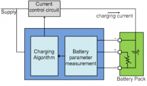
From the charging profile, it is understood that a controlled current source is required for a single-cell Li-Ion battery charger, which needs to be altered, depending on the battery state. Considering these requirements, the following functional blocks are required for a microcontroller-based implementation:
- Current control circuit
- Battery parameter (Voltage, current, temperature) measuring circuit
- Charging algorithm (for implementing CC-CV profile)
This is shown in figure 2.
The current control circuit can be built using a voltage source and a current feedback. It works like a typical negative feedback control system. The feedback is taken by allowing the charging current to pass through a small resistor, thereby developing some voltage.
The voltage source can be created using two methods:
- Linear Topology
- Switching – Buck or Boost Topology
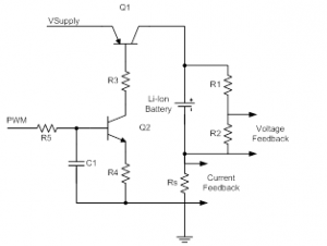
The linear topology uses a series pass element (either BJT or MOSFET) in linear mode as shown in figure 3.
The charging current is controlled by controlling the bias to the series pass transistor Q1. The bias can be controlled using a digital to analog converter (ADC) or pulse width modulator (PWM) with an external RC low pass filter. The linear method is suitable for low charging currents <1A, due to power dissipation in series pass element.
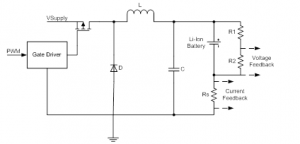
The switching topology uses its natural advantage of lower power consumption to achieve higher charging currents. Charger based on switching buck regulator is shown in figure 4.
The charging current is set by the duty cycle of the PWM driving the MOSFET.
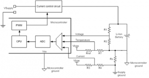
Battery parameter measurement circuit: Feedback signals need to be measured using an ADC, a peripheral available in most modern day microcontrollers. In figures 3 and 4, we saw how the battery voltage and current feedback is taken. However, these are differential signals that require a differential ADC for the measurement while typically single-ended ADCs are available in microcontrollers. The circuit shown in figures 4 and 5 can be easily modified to produce a single-ended signal for all three parameters – voltage, current and temperature – by making the microcontroller ground and supply ground different.
The battery negative terminal is made as the microcontroller ground. This makes voltage, temperature, and current feedback referenced to the microcontroller ground and allows for single-ended ADC measurement. For current feedback, a positive offset voltage needs to be introduced, as the feedback voltage will be negative when the battery is being charged. As shown in figure 5, resistor R3 and R4 provide the required offset voltage.
Charging algorithm: This action closes the loop. The CPU reads the ADC readings for battery voltage, charging current, and temperature and controls the PWM duty cycle according to the charging profile. The rate at which the CPU monitors the ADC results and controls the PWM depends upon the trade-off between loop response time and CPU bandwidth consumption.
ADC parameters and PWM resolution: ADC resolution and accuracy and PWM resolution are important parameters which should be considered while designing battery chargers. ADC resolution defines how precisely the input voltage can be measured (in this case, feedback voltages). PWM resolution defines how precisely you can change the duty cycle of the output signal, which in turn determines the output voltage of current control circuit. While charging Li-Ion batteries, the battery voltage needs to be accurately and precisely controlled. This is much more important when the battery voltage is near full charge. This controllability depends upon ADC resolution, accuracy in measurement, and granularity in duty cycle variation.
As an example, the charger architecture shown in Figure 5 has been implemented in a CY8C24x23 PSoC device from Cypress Semiconductor. The microcontroller is equipped with generic digital and analog blocks that can be configured to specific circuit functions. For example, continuous time analog blocks can be used to implement the programmable gain amplifier and comparator.
Switched capacitor analog blocks have a wide variety of uses, including filters, digital to analog converters (DAC), and analog to digital converters (DAC). Digital basic blocks can be used to implement the PWM, counters, timers, and buffers while digital communication blocks are used to implement communication interfaces such as SPI, UART, IrDA RX and TX. The device also provides I2C block which can function as master or slave.
As this article illustrates, through having properly designed charging circuitry, it is possible to reduce the system cost and the size of the battery required, granting designers’ greater flexibility. By using a microcontroller such as the the CY8C24x23 PSoC device from Cypress Semiconductor, designers are able to not only have the advantages afforded by properly designed charging circuitry, but are also offered configurability options, as well as having the ability to integrate other functions such as battery state of charge (SOC) calculation.
Pushek Madaan and Rajiv Badiger
Contenuti correlati
-
FBDi association: EU battery regulation on the finish line
With a large majority, the EU Parliament adopted the Council position on the new EU Battery Regulation, which is to replace the previous EU Battery Directive of 2006. There were hardly any changes to the underlying draft...


